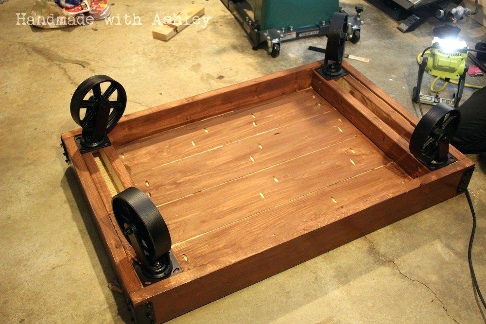
Industrial retractable caster wheels DIY
Don't forget to smash that like button with the grinder complete stand.
I need a way to move it around. I bought some of these high-test wheels, 300 pound wheels. I'd like to put them underneath the stand. However I want the ability to retract them so it'll sit solid on that sturdy base that I made. I got some 3/4 inch steel rod. That I think will sleeve over that to create some bushings and this acne or trapezoidal thread that I'm hoping will help me force it up and down like a lead screw. Get some quarter-inch cold-rolled. I'll cut some patterns out of those for the brackets and wheel hubs for lack of a better description so let's see what can't do. I've got the brackets laid out here.

The parallelogram that I'm hoping will raise and lower the wheels initially. I had designed it to have two lead screws so the top of the parallelogram could move when the lead screw would affect both pivot points, but I realized where the crank is would need to be able to raise and lower as that parallelogram raised and lowered. So I went to a different approach. Cut these two dog bones out and the parallelogram now is going to have a link in the middle. So this lead screw push it forward and back so the connector now is these two dog bones. These will be the two axles down here on the bottom and as the lead screw pushes or pulls this away. This parallelogram will be forced either down or up now the wheels pivot off of here below so they'll be on a similar swinging pendulum down here. So the next steps is to weld these to the axle.


These uprights I went with a little longer lever here, hoping to get some force with that lead screw and then of course weld the wheels to the same axle. The tough thing with that is all going to have to be welded in place to ensure that the angles are right and that nothing binds when it moves. So I'm gonna disassemble the belt grinder flip it up on its head and see if we can't get this done. So I've got the linkage marked up here, just got attacked. Make sure these stay in phase as you can see the side pieces are also tacked in. They of course hold the axis for the wheels themselves. You can see the wheels are designed to cam underneath and lift the weight of this up if this all works right. This leadscrew act like a half night if you will when I feed this captured on this pivot.


It should pull this towards. This captured point camming the wheels underneath so I got it all locked up here. You’re gonna watch the first trial. Take this down yeah so it did camera. You see it's taking the four-way excellent now in. Reverse should set it back down on the feet. We need some stops. There see my lead screw doesn't pull out. I'm real happy with that. That's the first time any project of mine has ever worked. The first try I'm gonna weld this up disassemble. It still need to make a handle for this crank and then get some paint on it.

